💧 Sump Bubble Trap Calculator
Size aquarium sump baffles for slower flow, bubble rise time, microbubble risk, and glass or acrylic cut pieces.
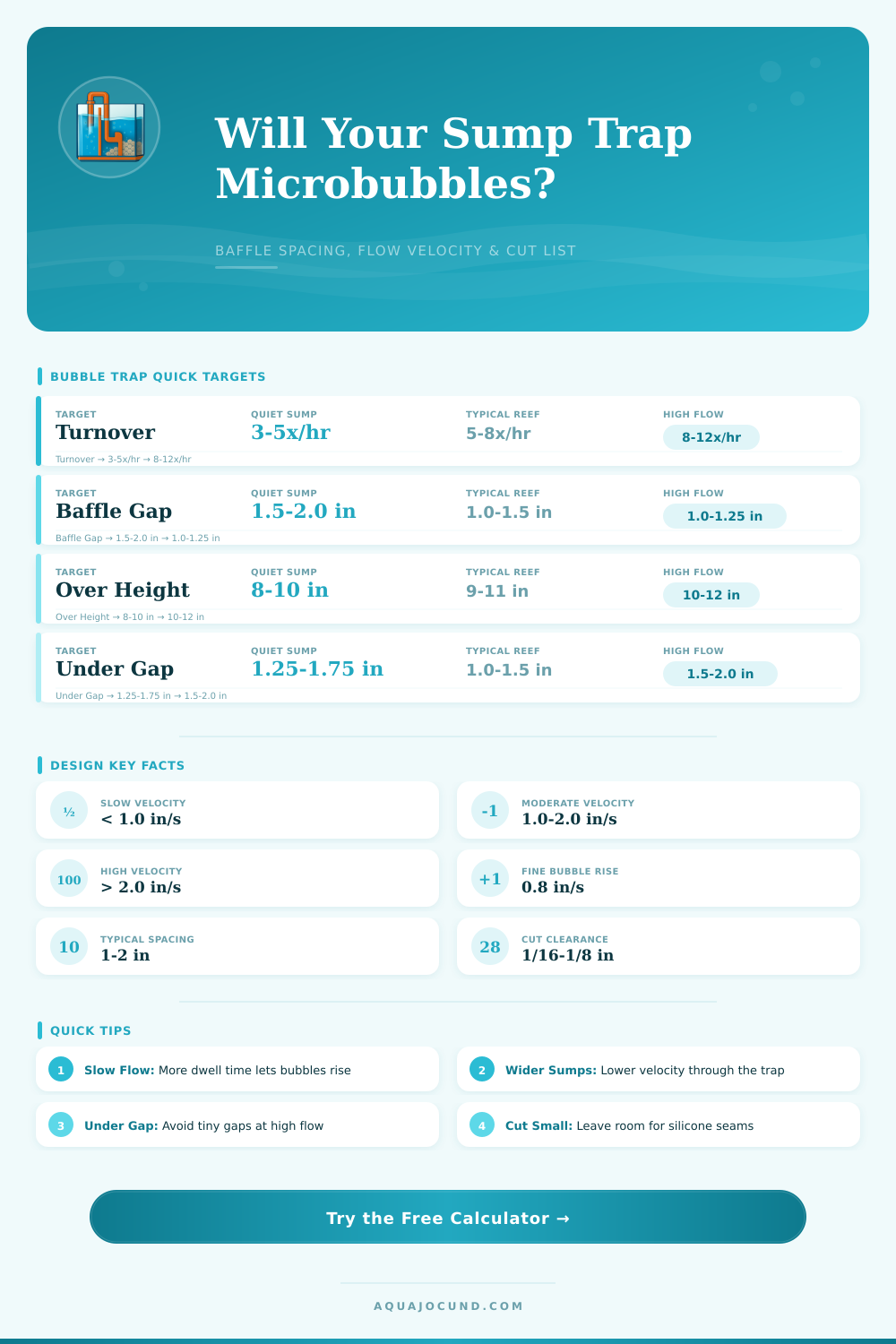
| Flow Style | Velocity Target | Spacing Target | Under Gap | Best Use |
|---|---|---|---|---|
| Very quiet | 0.5-0.8 in/s | 1.5-2.0 in | 1.25-1.75 in | Fine bubbles, skimmer sections |
| Typical reef | 0.8-1.2 in/s | 1.0-1.5 in | 1.0-1.5 in | Most return chambers |
| Compact sump | 1.2-1.8 in/s | 0.75-1.25 in | 1.0-1.5 in | Limited cabinet space |
| High flow | 1.8-2.5 in/s | 1.25-2.0 in | 1.5-2.25 in | Needs socks, roller, or foam help |
| Material | Nominal Thickness | Typical Kerf | Suggested Side Clearance | Notes |
|---|---|---|---|---|
| 1/8 in glass | 3.2 mm | 1/16 in | 1/16 in per side | Small freshwater sumps |
| 1/4 in glass | 6.0 mm | 1/16 in | 1/16-1/8 in per side | Common glass sump baffles |
| 3/8 in glass | 10.0 mm | 3/32 in | 1/8 in per side | Large or tall baffles |
| 1/4 in acrylic | 6.0 mm | 1/8 in | 1/8 in per side | Use acrylic-safe bonding when possible |
| 1/4 in PVC sheet | 6.0 mm | 1/8 in | 1/8 in per side | Opaque, easy to cut |
| Display / Sump | Typical Flow | Width | Water Depth | Typical Trap |
|---|---|---|---|---|
| 20 gal nano / 10 gal sump | 120-200 gph | 10 in / 25 cm | 7-8 in / 18-20 cm | 1 in spacing, 1 in under gap |
| 40 breeder / 20 long sump | 250-400 gph | 12 in / 30 cm | 8-9 in / 20-23 cm | 1.25 in spacing, 1.25 in gap |
| 75 reef / 29 gal sump | 350-600 gph | 12 in / 30 cm | 9-10 in / 23-25 cm | 1.25-1.5 in spacing |
| 120 reef / 40 breeder sump | 500-900 gph | 18 in / 46 cm | 9-11 in / 23-28 cm | 1.5 in spacing, 1.5 in gap |
| 180 reef / 75 gal sump | 800-1400 gph | 18 in / 46 cm | 10-12 in / 25-30 cm | 1.5-2 in spacing |
A sump is an device that returns clean water to your reef tank. Additionally, a properly functioning sump will prevent bubbles from moving into your display tank. If the sump isnt functioning correct, the bubbles will move from the sump into the display tank and be circulated to the coral.
Bubbles are often thought to be cause by the protein skimmer or the drain in the sump tank. The real cause of the bubbles is the velocity of the water in the final chamber of the sump. The velocity of the water will determine if the bubbles will reach the surface of the water before they are drawn into the return pump of the sump.
Stop Bubbles by Fixing Sump Size and Water Flow
The rate at which bubbles rises within the sump can vary depending upon the size of the bubbles. For instance, the fine mist created by the protein skimmer will cause the bubbles to travel slow to the surface of the sump. Bubbles created by the drain will travel more quick to the surface of the sump.
If the velocity of the water is too fast within the final chamber of the sump, the bubbles will not be able to reach the surface before the return pump of the sump pulls the water. A calculator can help with determining the proper velocity of the water in the sump. To use the calculator, you will need to input the flow rate of the sump, the width of the sump, the depth of the water in the sump, and the type of bubbles that is being created within the sump tank.
Based upon these parameter, the calculator will display whether the velocity of the water is too fast for the sump. Another variable that can be manipulated within the sump is the dimensions of the sump itself. By changing the dimensions of the sump, the builder can alter the velocity of the water within that sump.
For instance, if the builder makes the sump wider or if the depth of the sump is increased, the velocity of the water will decrease. This is due to the increased area of the sump that the water can fill. Conversely, if the sump is made narrower or shallower, the water velocity will increase.
This is another reason that many sumps that are created in a compact area may have issue with the velocity of the water and result in bubbles being created within the sump. These variables are represented for the builder in the sump velocity calculator to help make certain that the dimensions of the sump are created to ensure that the velocity of the water will be within the proper range. Another factor within the sump that will impact the velocity of the water is the spacing between the baffles of the sump.
If the baffles are spaced closely together, the velocity of the water will be high through those narrow gap in the sump. Additionally, high velocities of the water through narrow channels will cause the formation of bubbles that will be pushed into the next chamber of the sump. If the baffles are spaced farther apart, the velocity of the water will be reduced.
However, if the gaps between the baffles is too large, the water may slosh over the baffles during a power outage in the sump tank. The sump velocity calculator accounts for this potential problem for the user by calculating both the velocity of the water within the sump and the velocity of the water sloshing over the baffles. Based upon these two calculation, the calculator will provide the builder with the proper spacing between the baffles of the sump.
The last factor that contributes to the proper functioning of a sump is the gap located under the baffles of the sump. The builder of the sump must consider this gap to ensure that the return pump does not pull the bubbles downward into the sump. If the gap is too narrow under the baffles during high flow rate of water through the sump, the narrow gap will create a channel of fast moving water that will pull any bubbles that are created downward within the sump.
Additionally, the sump velocity calculator accounts for this issue in that it calculates the velocity of the water under each baffle separately from the average velocity of the water within the sump. Additionally, the sump velocity calculator can calculate the proper size for the gap under each baffle. Many reef tank builders ignore this step in the sump building process and as a result, find that their bubble trap begin to fail when they increase the flow rate of their return pump.
The material that is used to build the sump tanks will impact the dimensions of the sump tank. For instance, if the sump is built with thick glass or thick acrylic materials, those materials will take up some of the area for the water within the sump. The sump velocity calculator accounts for this issue for the sump builder in that the calculator allows the user to input the thickness of the sump tank material.
Based upon this input from the builder, the calculator can subtract the area that the baffles will take up from the total measurements that are provided to ensure that there is enough space within the sump tanks for the water to flow through the channels created in the sump. Real world factors can change the way that a sump tank will function. For instance, factors such as salt creep and detritus can reduce the size of the gaps between the baffles in the sump.
As a result, the sump that was once bubbling free of bubbles may begin to push microbubbles into the display tank. In this situation, the numbers can be entered into the sump velocity calculator again to determine if the sump is still created in a way that will prevent bubbles from forming within the sump. While the goal of the sump is not to have zero bubbles at any flow rate of water through the sump, the goal is to create a bubble trap that will remain effective in its function within the normal range of flow rates of the reef tank system.
If the sump velocity calculator displays a low risk of the formation of microbubbles, the sump is performing its job effective.