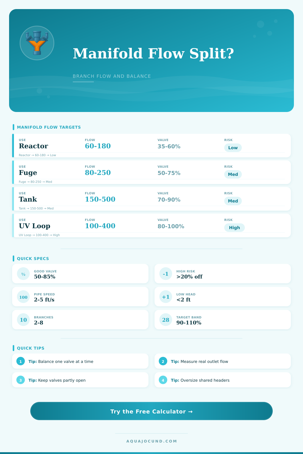
Manifold Flow Split Calculator
Estimate pump flow split across aquarium manifold branches, valve restriction, branch head loss, pipe velocity, target match, and imbalance risk.
Calculation Breakdown
| Branch Use | Typical Flow | Target Tolerance | Balance Note |
|---|---|---|---|
| Small media reactor | 60-120 GPH / 227-454 L/h | 80-120% | Gentle tumble or contact time matters more than raw flow. |
| Carbon or GFO reactor | 40-160 GPH / 151-606 L/h | 85-115% | A tight valve can collapse the branch flow quickly. |
| Refugium feed | 80-250 GPH / 303-946 L/h | 75-125% | Usually accepts moderate variance if overflow level is stable. |
| UV sterilizer loop | 100-400 GPH / 379-1514 L/h | 90-110% | Stay close to the target dwell-time flow for the unit. |
| Auxiliary tank return | 150-500 GPH / 568-1893 L/h | 90-115% | Check overflow capacity and sump level after tuning. |
| Frag tank feed | 200-700 GPH / 757-2650 L/h | 85-120% | High turnover branches need larger pipe to avoid noisy jets. |
| Valve Opening | Approx Flow Factor | Use Case | Risk |
|---|---|---|---|
| 25% | About 8% | Fine trimming only | Easy to clog or drift out of balance. |
| 40% | About 19% | Restricting a small reactor | Large flow change from small handle movement. |
| 60% | About 40% | Common balancing point | Workable if pump capacity is generous. |
| 80% | About 67% | Preferred daily range | Lower restriction and easier repeat tuning. |
| 100% | 100% | Low restriction branch | May steal flow from tighter branches. |
| System | Typical Pump At Manifold | Branch Count | Typical Target Per Branch |
|---|---|---|---|
| 20 gal sump | 250-450 GPH / 946-1703 L/h | 2-3 | 60-120 GPH / 227-454 L/h |
| 40 breeder reef | 450-750 GPH / 1703-2839 L/h | 3-4 | 90-180 GPH / 341-681 L/h |
| 75 gal reef | 700-1200 GPH / 2650-4542 L/h | 3-5 | 120-250 GPH / 454-946 L/h |
| 125 gal display | 1100-2000 GPH / 4164-7571 L/h | 4-6 | 180-400 GPH / 681-1514 L/h |
| Fish room rack | 1200-3000 GPH / 4542-11356 L/h | 6-12 | 80-250 GPH / 303-946 L/h |
| Small pond rack | 2000-4500 GPH / 7571-17034 L/h | 4-10 | 250-700 GPH / 946-2650 L/h |
| Branch Velocity | Flow Behavior | Likely Adjustment | Manifold Effect |
|---|---|---|---|
| Under 1.5 ft/s / 0.46 m/s | Very gentle | Use smaller outlet or more pump if target is missed. | Low friction but weaker purge velocity. |
| 1.5-3 ft/s / 0.46-0.91 m/s | Calm and efficient | Good range for reactors and refugium feeds. | Easy to balance with modest valve changes. |
| 3-5 ft/s / 0.91-1.52 m/s | Active branch flow | Good for tank feeds and UV loops. | Friction starts to matter on long branch runs. |
| 5-7 ft/s / 1.52-2.13 m/s | High velocity | Increase pipe size or reduce branch target. | Greater imbalance risk between unequal branches. |
| Above 7 ft/s / 2.13 m/s | Noisy or restrictive | Use larger pipe, fewer bends, or more branches. | Small valve changes cause large flow changes. |
| Added Branch Head | Flow Drop Trend | Common Cause | Balance Response |
|---|---|---|---|
| 0-1 ft / 0-0.3 m | Small | Short equal tubes | Valve tuning is usually enough. |
| 1-3 ft / 0.3-0.9 m | Moderate | Reactor body, elbows, vertical lift | Open that branch more than nearby outlets. |
| 3-5 ft / 0.9-1.5 m | Large | UV unit, canister loop, long hose | Consider dedicated feed or larger branch pipe. |
| Over 5 ft / 1.5 m | Severe | Long rack run or restrictive device | Expect imbalance unless the header is oversized. |
This is a manifold flow split calculator. You buy fancy corals, set up a sump, hook everything up and start running the tank. Next thing you know, the plumbing is fighting itself… some of the reactors has minimal water while others flood. Why? Because the header of that manifold wasn’t meant to deal with flow physics. This is frustrating and all too common among those who don’t bother to balance their systems.
Plug in your branch configuration and pump size into the manifold flow split calculator. Let it do the math for you so you won’t waste time wondering if you’re making noise or actualy opening and closing valves.
How to Balance Your Manifold Flow
More resistance = less water; Water always flows down path of least resistance. That means a device placed on a branch with lower pressure loss will steal water from another device until the pressure are equal. This means harder-to-reach devices gets starved. Valves aren’t just on-off switches; they’re dynamic restrictors which change the balance of the system.
When I account for elevation, friction and valve restriction, what flow actualy gets to each point? It’s not about getting all branches to 120 gallons per hour precisely. That rarely happen. It’s about whether or not the variance is acceptable, or whether the system is basicly unbalanced. Most people don’t realize that while valve position matters a lot, it’s just one part of bigger picture that includes pipe diameter, velocity, and header layout.
Closing a ball valve almost all the way seems to shut off most of the water, giving you nice fine tuning. But realy, the water is turbulent where it comes out and changes with small movements. The best results are from leaving valves mostly open, as indicated by tables on the page. Generally speaking, leave them at 50-80% open. Anything tighter will throw off the whole balance. You will have a bunch of branches with lower flow because they suddenly gets a big pressure drop after you close one down to far. That’s also why the calculator warns about risking an imbalanced system if the valve that’s most closed is too narrow compared to the rest.
There are also quiet variables like pipe diameter and velocity. The narrower the pipe, the greater the friction losses, which consume pump head before it can reaches the outlet. For example, if you run long lengths with small tubing, you may need extra pump power simply to compensate for internal drag. By taking account of typical branch head loss and inner diameter of your pipes, the calculator factors in these details and provides an estimate. This will give you some idea as to whether your hardware is choking the flow.
You’ll want enough speed to keep debris suspended, while avoiding creating excessive wear and tear on fittings and loud jets of water. Two to five feet per second is generally considered efficient flow without turning your sump into a wind tunnel.
The other surprisingly important factor is that header layout also matter. Branches nearest to the inlet do best with an end fed header, where water enters from only one direction and leaves via a row of ports. With a looped or center fed header, the water has less distance to travel to every port, distributing pressure more uniformly. By default, the calculator assumes you are using an end fed header, but if not you can adjust this setting and it will modify its estimate according. This shows how shape affects physical behavior. While it seems minor during planning, it could of save you from having to replace your pipes months later after realizing your distant reactor isn’t getting enough flow.
In the end, it all comes down to tradeoffs. Narrow pipes mean higher head loss (less flow). Valves always restrict something, but what? And then there are different devices… so which go where and how do I keep them in line? The calculator provides a starting point so that you know if your design has legs, before cutting your first piece of PVC. It brings the theory behind hydraulics into real-world terms, giving you numbers against which you can compare what your reactor requires.
With an understanding of how the parts fit together, balancing a manifold becomes less of a guessing game and more of an exercise in engineering. It is less about chasing perfect symmetry and more about pursuing functional stability. The corals is happy. The pumps are quiet.